Description
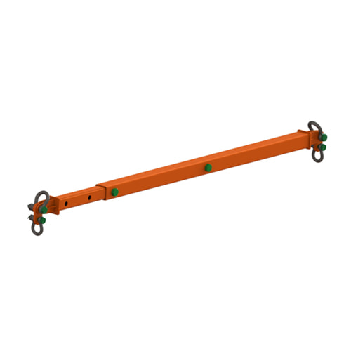
The Britlift telescopic spreader beam is the perfect solution for quick adjustment! Built to order.
Slightly heavier than a modular equivalent, a telescopic spreader beam allows for quick sliding adjustment between lengths and adjustment points can be as little as 50mm apart giving a huge amount of flexibility.
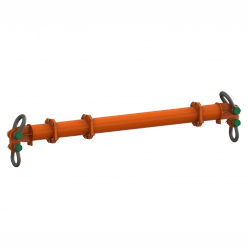
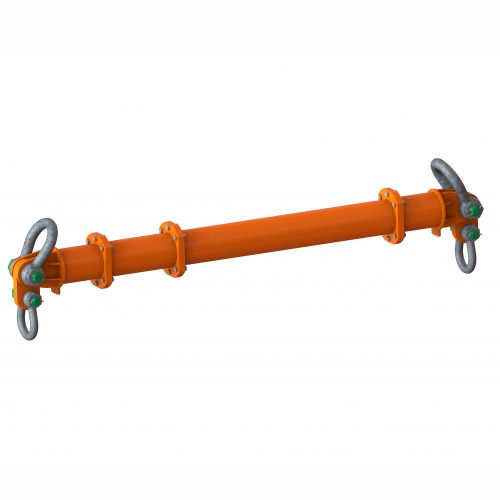
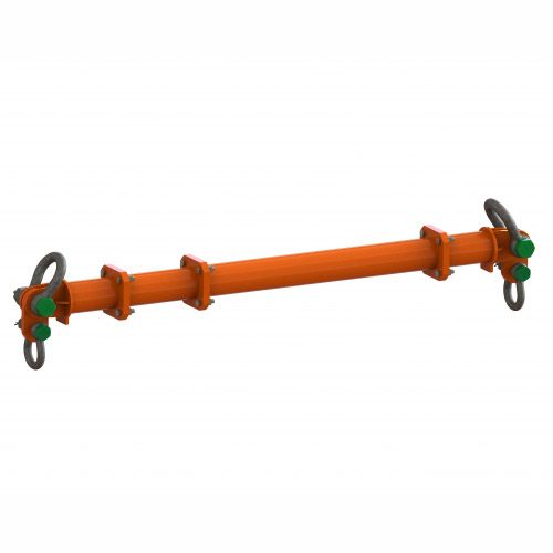
This set of user instructions is for various types and sizes of Britlift telescopic Spreader Beams. The information in this set of user instructions is generalised to suit all of the beams listed below, covering all the necessary points and gives a clear guide on how to use this.
Specifications
| DESCRIPTION | SELF WEIGHT | TOP SHACKLES | BOTTOM SHACKLES | ADJUSTMENT (MM) |
| TELE-4 Telescopic Spreader Beam—1.5m-2.5m | 30 | 6.5 Tonne | 4.75 Tonne | 125 |
| TELE-4 Telescopic Spreader Beam—2.5m-4m | 45 | 6.5 Tonne | 4.75 Tonne | 250 |
| TELE-8 Telescopic Spreader Beam—1.5m-2.5m | 35 | 6.5 Tonne | 4.75 Tonne | 125 |
| TELE-8 Telescopic Spreader Beam—2.5m-4m | 50 | 6.5 Tonne | 4.75 Tonne | 250 |
| TELE-12 Telescopic Spreader Beam—1.5m-2.5m | 50 | 12 Tonne | 8.5 Tonne | 125 |
| TELE-12 Telescopic Spreader Beam—2.5m-4m | 80 | 12 Tonne | 8.5 Tonne | 250 |
| TELE-12 Telescopic Spreader Beam—4m-6m | 120 | 12 Tonne | 8.5 Tonne | 250 |
| TELE-16 Telescopic Spreader Beam—1.5m-2.5m | 55 | 12 Tonne | 8.5 Tonne | 125 |
| TELE-16 Telescopic Spreader Beam—2.5m-4m | 85 | 12 Tonne | 8.5 Tonne | 250 |
| TELE-16 Telescopic Spreader Beam—4m-6m | 125 | 12 Tonne | 8.5 Tonne | 250 |
![]() GENERAL SAFETY REQUIREMENTS
GENERAL SAFETY REQUIREMENTS ![]()
- THE WORKING LOAD LIMITS OF THESE SPREADERS (4 TONNES, 8 TONNES, 12 TONNES AND 16 TONNES) MUST NOT BE EXCEEDED UNDER ANY CIRCUMSTANCES.
- ENSURE THAT THE LINK PLATES (WHICH EACH HAVE A WORKING LOAD LIMIT OF HALF OF THE WORKING LOAD LIMIT OF THE BEAM) HANG DOWN, AND THAT THE APPROPRIATE BOTTOM SHACKLES (SEE CHART 1) ARE CONNECTED TO THE BOTTOM HOLES OF THE LINK PLATES.
- ADJUSTMENT OF THE SPAN OF THE SPREADER IS CARRIED OUT BY REMOVING THE LOAD PINS AND SLIDING THE INNER BEAM MEMBER TO THE REQUIRED SPAN WHILST ENSURING THAT THE HOLES IN THE OUTER BEAM MEMBER ARE ALIGNED WITH THE MATCHING PAIR OF HOLES IN THE INNER BEAM MEMBER.
- ONCE THE SPREADER BEAM HAS BEEN ADJUSTED TO THE REQUIRED SPAN AND THE HOLES ARE ALIGNED, THE LOAD PINS ARE TO BE FITTED AND SECURED USING THE SHACKLE PIN NUTS AND COTTER PINS.
- ANY PERSONNEL USING THIS PRODUCT MUST BE A TRAINED AND COMPETENT RIGGER OR SLINGER/SIGNALER.

