
Misuse of Spreader Beams
Firstly, I would like to thank everyone who read, commented, liked and shared the first post in this series, Spreader Beam Or Lifting Beam – An Explanation For All. The response was fantastic with thousands of views, over 650 likes and over 100 shares. If you missed the article please click the link above – as in this piece I will be building on what was covered there.
Today I’m going to look at the misuse of spreader beams which is still shockingly common in the industry. I will be showing some images and diagrams and discussing what is incorrect and why.
Disclaimer: The content in this article is aimed to educate and improve safety in lifting. I will be editing photos to remove any and all branding – I have no interest in laying blame to anyone for these lifting errors and only wish to help stop these incidents from happening again. Anyone who attempts to identify any personnel or businesses involved in any of the lifting operations will have their comments removed.
The Example

Figure 1
Figure 1 was taken of a very recent lift within the UK in 2017. One of the companies involved used this as a promotional image.
Now I’m sure many of you have already spotted the error with this lift, but I’m going to look at not just what is wrong, but why it is wrong.
As discussed in my first article, a spreader beam is subjected to a crushing force – compression, if you need to recap why, please re-read the section in my first article with the children on the swing.
To help explain what is going on in the above image, I’ve redrawn it below:

Figure 2
To help explain what is going on in the above image, I’ve redrawn it (see Figure 2).
It is difficult to be sure from the photo, so to start with in figure 2 I have assumed that bottom slings maintain the same angle as the top slings (it actually looks as if the ISA angle widens which I will deal with later in this post).
What is happening here?
Let’s get straight to the point then, the beam in this image isn’t being used correctly, in fact, you could say the beam in this image isn’t even being used!
In this example, the compression force is entirely taken by the load itself – indicated by the red arrows in figure 2. When presented with the above scenario, many would argue that the spreader beam would perhaps share the compression force with the load, but this is not the case.
The first point to make is that if the spreader beam was removed from this there would be no change to the sling angle and no change to the forces in the load.
The reason the load takes all of the compression in this example, is because this is the point at which the force pulling downwards (created from the weight of the load) travels into the angled sling. As discussed in my first article, it is the angled sling which creates the inwards (compression) force, and in this example this force acts at the point where the angles change.
Compare the Diagrams
Higher up the rig, where the spreader beam is placed there is no change in the angle of the force from the bottom slings to the top slings, therefore there is no resultant force created to compress the spreader.
To help put this into perspective I have redrawn the diagram with the slings underneath the spreader beam having a wider ISA angle than those above.

Figure 3
Let’s compare this new diagram (figure 3) to the first (figure 2). Starting at the bottom with the load, and the bottom set of slings, we have a very similar situation.
The load will still be in compression for the same reasons as in figure 2. When we move up to the spreader however, we now have a slightly different situation.
We now have a change in angle between the bottom slings and the top slings which means we will also have a resultant force passing into the spreader beam.
In this case however the force passing into the beam will be tension (pulling force) and not the compression (crushing force) the beam was designed for.
Contact us today
Our engineers are available for a free consultation
to help you find the right equipment for your lift.
Enjoyed the article and communicated in a manner that is easily understood – Leslie Anderson, Stage 4 Rigger at Aker Solutions
Still not convinced?

Figure 4
Have a look at the diagram on the right. In figure 4 image 1, two buckets are hanging from separate slings in a crane hook.
In figure 4 image 2 a man has stepped between the buckets and is pushing the slings apart. The slings want to hang straight so the man is experiencing a compression force on his arms.
This is similar to the forces on a spreader when it is being used correctly.
In figure 4 image 3 the buckets are now connected by a bar. The slings are at an angle from the bar to the hook and this angle does not change as they pass the man’s arms. Here the man is doing nothing and is experiencing no compression force.
In figure 4 image 4 the bar has been lengthened and the man is now holding the slings in. Quite clearly here the man would be experiencing a pulling force. This is the same as the spreader in figure 3, the change in angles here produces a tensile force.
Great article again Anthony. Well written and informative. Thanks for taking the time to put it together. – Kevin Bennison, MD at SWL Training
So why is this misuse?
The example in figure 2 shows a beam that is not really being used, in this example it is unlikely that a beam would fail – the issue is more likely to be with the load. If it has been assumed that the spreader will be taking the compression forces out of a load, where in reality the load is bearing all of the force, the load could be damaged or even drop.
The example in figure 3 is much worse, the same problems are present as in figure 2, but in this example the beam itself could fail as they are not designed for tension. True tension and compression are similar forces, but a component such as the bolts in a modular spreader are calculated under the assumption that they will see stresses as a result of shear and bending – axial tension would add to these forces, something which was not allowed for in the design process.
In summary
In the example I have looked at today, the sling angles below the spreader were the particular area where misuse was present. To be clear, I am not suggesting that the slings below a spreader cannot be angled at all. In fact, it is mandatory to allow for a 6 degree (from vertical) angle as a minimum in accordance with the current EU harmonized standard (EN 13155:2003+A2:2009) for the design of spreader beams. In the case looked at today the angle was just a little too far away from vertical.
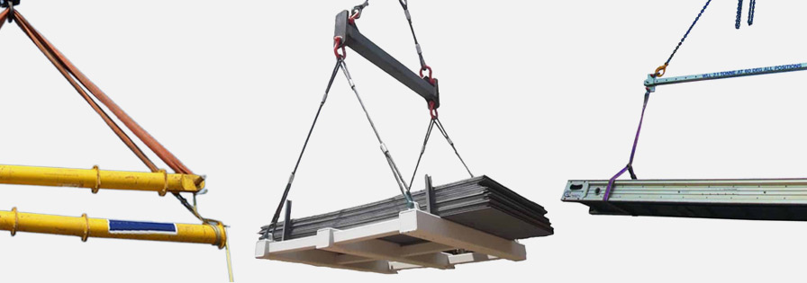
Originally, I intended to look at multiple examples of misuse in this post, so I hope you will forgive me for discussing this particular one at length. Instead, let me leave you with the following examples to discuss in the comments, I’ll be interested to hear your thoughts.
Thanks for reading and if you would like to stay up to date as these articles come out then please follow Britlift on Linkedin.
Anthony Culshaw
Anthony is currently the Technical Director at spreader and lifting Beam manufacturers Britlift. He is a former member of the LEEA Technical Committee and has spoken at lifting conferences around the world on the subject of below the hook lifting equipment.
Other examples


Hello Anthony. I´ve read this and your previous article and wonder why Figure 3 is considered a misuse. Would you be so kind to share your thoughts? Thanks and best regards from Barranquilla, Colombia
Hi Adolfo, Thank you for your interest in this technical piece, and for taking the time to enquire. A quick answer to your question is, yes this is misuse because the spreader beam is seeing tension forces that it hasnt been designed for. A spreader beam is designed ONLY for compression forces (through the beam), with the tension forces being seen within the loose link plates at either end. If you are referring to the third image in ‘other examples’ at the end of the article, then this is considered misuse because the hooks are the wrong way around.